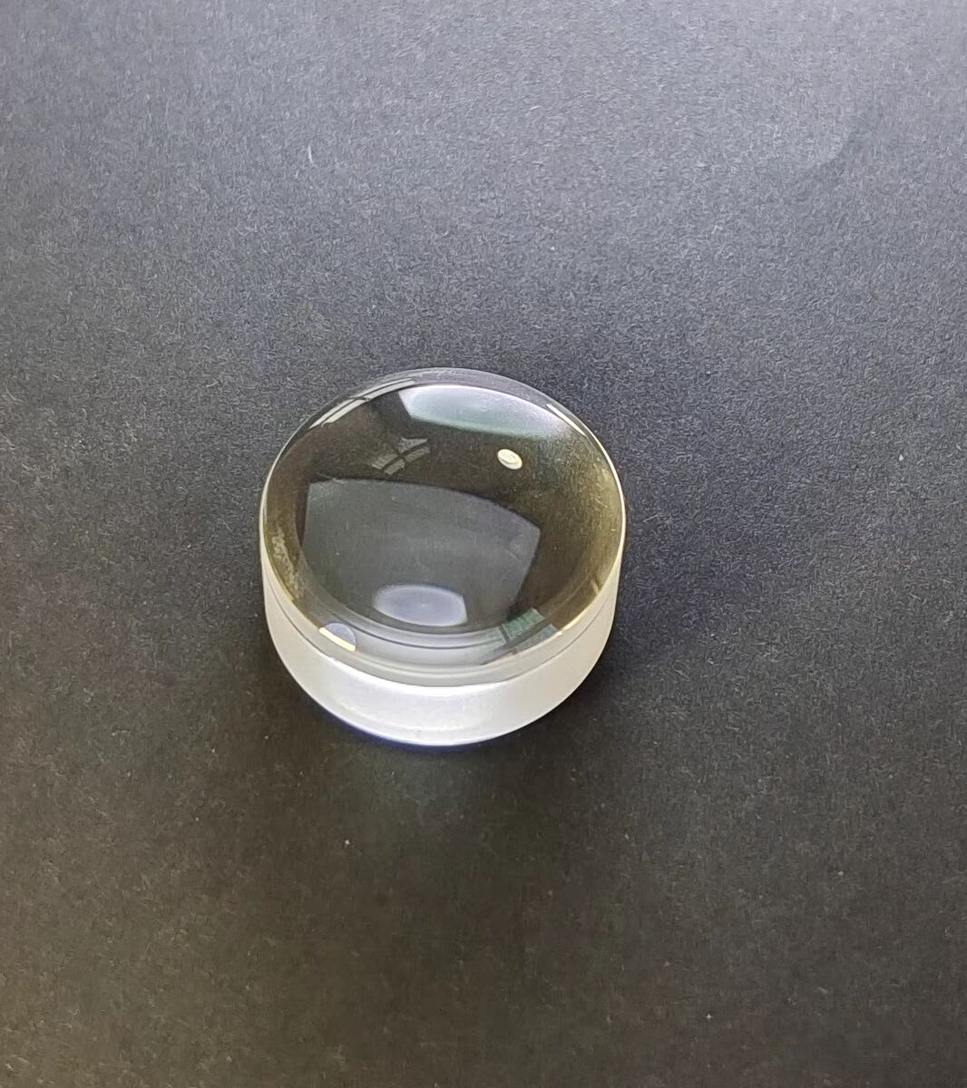
Manufacturing Specifications
Diameter Tolerance
The diameter tolerance of a circular optical component provides the acceptable range of values for the diameter.
Center Thickness Tolerance
The center thickness of an optical component, most notably a lens, is the material thickness of the component measured at the center. Center thickness is measured across the mechanical axis of the lens, defined as the axis exactly between its outer edges. Variation of the center thickness of a lens can affect the optical performance because center thickness, along with radius of curvature, determines the optical path length of rays passing through the lens. Typical manufacturing tolerances for center thickness are: +/-0.20 mm for typical quality, +/-0.050 mm for precision quality, and +/-0.010 mm for high quality.
Radius of Curvature
The radius of curvature is defined as the distance between an optical component's vertex and the center of curvature. It can be positive, zero, or negative depending on whether the surface is convex, plano, or concave, respectfully. Knowing the value of the radius of curvature allows one to determine the optical path length of rays passing through the lens or mirror, but it also plays a large role in determining the power of the surface. Manufacturing tolerances for radius of curvature are typically +/-0.5, but can be as low as +/-0.1% in precision applications or +/-0.01% for extremely high quality needs.
Centering
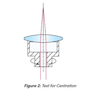
Centering, also known by centration or decenter,
The mechanical axis of a lens is simply the geometric axis of the lens and is defined by its outer cylinder. The optical axis of a lens is defined by the optical surfaces and is the line that connects the centers of curvature of the surfaces. To test for centration, a lens is placed into a cup upon which pressure is applied. The pressure applied to the lens automatically situates the center of curvature of the first surface in the center of the cup, which is also aligned with the axis of rotation .The mechanical axis of a lens is simply the geometric axis of the lens and is defined by its outer cylinder. The optical axis of a lens is defined by the optical surfaces and is the line that connects the centers of curvature of the surfaces. To test for centration, a lens is placed into a cup upon which pressure is applied. The pressure applied to the lens automatically situates the center of curvature of the first surface in the center of the cup, which is also aligned with the axis of rotation
Parallelism
Parallelism describes how parallel two surfaces are with respect to each other. It is useful in specifying components such as windows and polarizers where parallel surfaces are ideal for system performance because they minimize distortion that can otherwise degrade image or light quality. Typical tolerances range from 5 arcminutes down to a few arcseconds.
Angle Tolerance
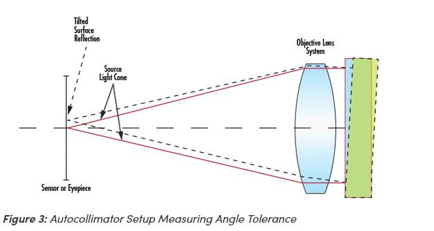
In components such as prisms and beamsplitters, the angles between surfaces are critical to the performance of the optic. This angle tolerance is typically measured using an autocollimator assembly, whose light source system emits collimated light. The autocollimator is rotated about the surface of the optic until the resultant Fresnel reflection back into it produces a spot on top of the surface under inspection. This verifies that the collimated beam is hitting the surface at exactly normal incidence. The entire autocollimator assembly is then rotated around the optic to the next optical surface and the same procedure is repeated.
Bevel
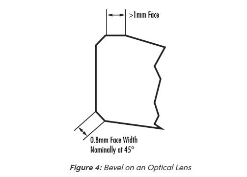
Glass corners can be very fragile, therefore, it is important to protect them when handling or mounting a component. The most common way of protecting these corners is to bevel the edges. Bevels serve as protective chamfers and prevent edge chips. They are defined by their face width and angle (Figure 4).
Clear Aperture
Clear aperture is defined as the diameter or size of an optical component that must meet specifications.
Surface Quality
The surface quality of an optical surface describes its cosmetic appearance and includes such defects as scratches and pits, or digs. In most cases, these surface defects are purely cosmetic and do not significantly affect system performance, though, they can cause a small loss in system throughput and a small increase in scattered light.
Surface Flatness
Surface flatness is a type of surface accuracy specification that measures the deviation of a flat surface such as that of a mirror, window, prism, or plano-lens. This deviation can be measured using an optical flat, which is a high quality, highly precise flat reference surface used to compare the flatness of a test piece. When the flat surface of the test optic is placed against the optical flat, fringes appear whose shape dictates the surface flatness of the optic under inspection. If the fringes are evenly spaced, straight, and parallel, then the optical surface under test is at least as flat as the reference optical flat. If the fringes are curved, the number of fringes between two imaginary lines, one tangent to the center of a fringe and one through the ends of that same fringe, indicate the flatness error. The deviations in flatness are often measured in values of waves (λ), which are multiples of the wavelength of the testing source. One fringe corresponds to ½ of a wave. 1λ flatness is considered typical grade, λ/4 flatness is considered precision grade, and λ/20 is considered high precision grade.
Power
Power, a type of surface accuracy specification, applies to curved optical surfaces, or surfaces with power. It is tested in a fashion similar to flatness, in that a curved surface is compared against a reference surface with a highly calibrated radius of curvature. Using the same principle of interference caused by the air gaps between the two surfaces, the interference’s pattern of fringes is used to describe the deviation of the test surface from the reference surface
Irregularity
Irregularity, a type of surface accuracy specification, describes how the shape of a surface deviates from the shape of a reference surface. It is obtained from the same measurement as power. Regularity refers to the sphericity of the circular fringes that are formed from the comparison of the test surface to the reference surface. When the power of a surface is more than 5 fringes, it is difficult to detect small irregularities of less than 1 fringe. Therefore it is common practice to specify surfaces with a ratio of power to irregularity of approximately 5:1.
Surface Finish
Surface finish, also known as surface roughness, measures small scale irregularities on a surface. They are usually an unfortunate by-product of the polishing process. Rough surfaces tend to wear faster than smooth surfaces and may not be suitable for some applications, especially those with lasers or intense heat, due to possible nucleation sites that can appear in small cracks or imperfections. Manufacturing tolerances for surface finish range from 50Å RMS for typical quality, 20Å RMS for precision quality, and 5Å RMS for high quality.





 售前客服
售前客服